Hallo,
habe den Code nun einmal angepasst, sodass er mit dem LANC Protokoll funktioniert.
Konnte den Code von Milz leider großteils nicht verwenden, da die pulsein Funktion zum auslesen der Signale immer leichte Verzögerungen hevorrufte, und schlussendlich die Zoomfunktion leicht hakelte.
Evtl. ist dies auch mit der IR Steuerung derzeit so, aber meine ist derzeit noch unterwegs, somit konnte ich es noch nicht testen.
Beim jetzigen Code wird das RC Signal via Interrupts abgefragt, ist dann jedoch beim Atmega 168/328 auf 2 Pin's (2&3) beschränkt, welche jedoch für meine Zwecke ausreichend war.
Derzeit habe ich nur die 8-stufige Zoomfunktion, und Record EIN/AUS eingebaut. Werde es evtl. in den nächsten Tagen auf die Funktionalität des Code's von Milz seiner Steuerung ausbauen und zusammenführen, sodass man mit der selben Platine Lanc & IR Kommandos für 2 verschiedene Modelle gleichzeitig senden kann.
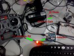
Genauere Beschreibungen zum Kabel und Funktion erkläre ich dann in einem neuen Thread, aber vielleicht kann ja schon mal jemand etwas damit anfangen.
Pinbelegung:
PPM/PWM Signal 1: Pin 2
PPM/PWM Signal 2: Pin 3
LANC cmd Pin: Pin 8
LANC lanc Pin: Pin 9
-------------------------------------------------------------
Arduino Code:
-------------------------------------------------------------
// Credits for LANC Part to Michael Koch
//
http://controlyourcamera.blogspot.co.at/2011/02/arduino-powered-lanc-remote.html
// Interrupt Part
#define PPM1_SIGNAL_IN 0 // Interrupt Port for Pin 2
#define PPM1_SIGNAL_IN_PIN 2 // Pin 2 of Interrupt 0
#define PPM2_SIGNAL_IN 1
#define PPM2_SIGNAL_IN_PIN 3
#define NEUTRAL_PPM1 1500
#define NEUTRAL_PPM2 1500
volatile int nPPM1In = NEUTRAL_PPM1; // volatile, we set this in the Interrupt and read it in loop so it must be declared volatile
volatile int nPPM2In = NEUTRAL_PPM2; // volatile, we set this in the Interrupt and read it in loop so it must be declared volatile
volatile unsigned long ulStartPeriod = 0; // set in the interrupt
volatile boolean bNewPPM1Signal = false; // set in the interrupt and read in the loop
volatile boolean bNewPPM2Signal = false; // set in the interrupt and read in the loop
// we could use nPPM1In = 0 in loop instead of a separate variable, but using bNewPPM1Signal to indicate we have a new signal
// is clearer for this first example
// LANC Part
#define cmdPin 8
#define lancPin 9
int cmdRepeatCount;
int bitDuration = 104; //Duration of one LANC bit in microseconds.
int recordstate = 0;
//Start-stop video recording
byte REC[] = {LOW,LOW,LOW,HIGH,HIGH,LOW,LOW,LOW, LOW,LOW,HIGH,HIGH,LOW,LOW,HIGH,HIGH}; //18 33
//Zoom in from slowest to fastest speed
byte ZOOM_IN_0[] = {LOW,LOW,HIGH,LOW,HIGH,LOW,LOW,LOW, LOW,LOW,LOW,LOW,LOW,LOW,LOW,LOW}; //28 00
byte ZOOM_IN_1[] = {LOW,LOW,HIGH,LOW,HIGH,LOW,LOW,LOW, LOW,LOW,LOW,LOW,LOW,LOW,HIGH,LOW}; //28 02
byte ZOOM_IN_2[] = {LOW,LOW,HIGH,LOW,HIGH,LOW,LOW,LOW, LOW,LOW,LOW,LOW,LOW,HIGH,LOW,LOW}; //28 04
byte ZOOM_IN_3[] = {LOW,LOW,HIGH,LOW,HIGH,LOW,LOW,LOW, LOW,LOW,LOW,LOW,LOW,HIGH,HIGH,LOW}; //28 06
byte ZOOM_IN_4[] = {LOW,LOW,HIGH,LOW,HIGH,LOW,LOW,LOW, LOW,LOW,LOW,LOW,HIGH,LOW,LOW,LOW}; //28 08
byte ZOOM_IN_5[] = {LOW,LOW,HIGH,LOW,HIGH,LOW,LOW,LOW, LOW,LOW,LOW,LOW,HIGH,LOW,HIGH,LOW}; //28 0A
byte ZOOM_IN_6[] = {LOW,LOW,HIGH,LOW,HIGH,LOW,LOW,LOW, LOW,LOW,LOW,LOW,HIGH,HIGH,LOW,LOW}; //28 0C
byte ZOOM_IN_7[] = {LOW,LOW,HIGH,LOW,HIGH,LOW,LOW,LOW, LOW,LOW,LOW,LOW,HIGH,HIGH,HIGH,LOW}; //28 0E
//Zoom out from slowest to fastest speed
byte ZOOM_OUT_0[] = {LOW,LOW,HIGH,LOW,HIGH,LOW,LOW,LOW, LOW,LOW,LOW,HIGH,LOW,LOW,LOW,LOW}; //28 10
byte ZOOM_OUT_1[] = {LOW,LOW,HIGH,LOW,HIGH,LOW,LOW,LOW, LOW,LOW,LOW,HIGH,LOW,LOW,HIGH,LOW}; //28 12
byte ZOOM_OUT_2[] = {LOW,LOW,HIGH,LOW,HIGH,LOW,LOW,LOW, LOW,LOW,LOW,HIGH,LOW,HIGH,LOW,LOW}; //28 14
byte ZOOM_OUT_3[] = {LOW,LOW,HIGH,LOW,HIGH,LOW,LOW,LOW, LOW,LOW,LOW,HIGH,LOW,HIGH,HIGH,LOW}; //28 16
byte ZOOM_OUT_4[] = {LOW,LOW,HIGH,LOW,HIGH,LOW,LOW,LOW, LOW,LOW,LOW,HIGH,HIGH,LOW,LOW,LOW}; //28 18
byte ZOOM_OUT_5[] = {LOW,LOW,HIGH,LOW,HIGH,LOW,LOW,LOW, LOW,LOW,LOW,HIGH,HIGH,LOW,HIGH,LOW}; //28 1A
byte ZOOM_OUT_6[] = {LOW,LOW,HIGH,LOW,HIGH,LOW,LOW,LOW, LOW,LOW,LOW,HIGH,HIGH,HIGH,LOW,LOW}; //28 1C
byte ZOOM_OUT_7[] = {LOW,LOW,HIGH,LOW,HIGH,LOW,LOW,LOW, LOW,LOW,LOW,HIGH,HIGH,HIGH,HIGH,LOW}; //28 1E
/*
Focus Control - not in Use
//Focus control. Camera must be switched to manual focus
byte FOCUS_NEAR[] = {LOW,LOW,HIGH,LOW,HIGH,LOW,LOW,LOW, LOW,HIGH,LOW,LOW,LOW,HIGH,HIGH,HIGH}; //28 47
byte FOCUS_FAR[] = {LOW,LOW,HIGH,LOW,HIGH,LOW,LOW,LOW, LOW,HIGH,LOW,LOW,LOW,HIGH,LOW,HIGH}; //28 45
byte FOCUS_AUTO[] = {LOW,LOW,HIGH,LOW,HIGH,LOW,LOW,LOW, LOW,HIGH,LOW,LOW,LOW,LOW,LOW,HIGH}; //28 41
*/
void setup() {
// LANC Part
pinMode(lancPin, INPUT); //listens to the LANC line
pinMode(cmdPin, OUTPUT); //writes to the LANC line
digitalWrite(cmdPin, LOW); //set LANC line to +5V
delay(5000); //Wait for camera to power up completly
bitDuration = bitDuration - 8; //Writing to the digital port takes about 8 microseconds so only 96 microseconds are left for each bit
// External Interrupt Part
attachInterrupt(PPM1_SIGNAL_IN,calcInputPPM1,CHANGE); // tell the Arduino we want the function calcInput to be called whenever INT0 (digital pin 2) changes from HIGH to LOW or LOW to HIGH
attachInterrupt(PPM2_SIGNAL_IN,calcInputPPM2,CHANGE); // catching these changes will allow us to calculate how long the input pulse is
}
void loop() {
// External Interrupt Signal Collection
if(bNewPPM1Signal)
{
bNewPPM1Signal = false;
bNewPPM2Signal = false;
}
// LANC Send
if(nPPM1In>1500 && recordstate==0)
{
recordstate = 1;
lancCommand(REC);
}
if(nPPM1In<1400 && recordstate==1)
{
recordstate = 0;
lancCommand(REC);
}
if (nPPM2In>1580 && nPPM2In<1629){lancCommand(ZOOM_IN_0);}
if (nPPM2In>1630 && nPPM2In<1679){lancCommand(ZOOM_IN_1);}
if (nPPM2In>1680 && nPPM2In<1729){lancCommand(ZOOM_IN_2);}
if (nPPM2In>1730 && nPPM2In<1779){lancCommand(ZOOM_IN_3);}
if (nPPM2In>1780 && nPPM2In<1829){lancCommand(ZOOM_IN_4);}
if (nPPM2In>1830 && nPPM2In<1879){lancCommand(ZOOM_IN_5);}
if (nPPM2In>1880 && nPPM2In<1929){lancCommand(ZOOM_IN_6);}
if (nPPM2In>1930){lancCommand(ZOOM_IN_7);}
if (nPPM2In<1420 && nPPM2In>1369){lancCommand(ZOOM_OUT_0);}
if (nPPM2In<1370 && nPPM2In>1319){lancCommand(ZOOM_OUT_1);}
if (nPPM2In<1320 && nPPM2In>1269){lancCommand(ZOOM_OUT_2);}
if (nPPM2In<1270 && nPPM2In>1219){lancCommand(ZOOM_OUT_3);}
if (nPPM2In<1220 && nPPM2In>1169){lancCommand(ZOOM_OUT_4);}
if (nPPM2In<1170 && nPPM2In>1119){lancCommand(ZOOM_OUT_5);}
if (nPPM2In<1120 && nPPM2In>1069){lancCommand(ZOOM_OUT_6);}
if (nPPM2In<1070){lancCommand(ZOOM_OUT_7);}
} // Loop End
// External Interrupt CalcInput Part
void calcInputPPM1()
{
if(digitalRead(PPM1_SIGNAL_IN_PIN) == HIGH)
{
ulStartPeriod = micros();
}
else
{
if(ulStartPeriod && (bNewPPM1Signal == false))
{
nPPM1In = (int)(micros() - ulStartPeriod);
ulStartPeriod = 0;
bNewPPM1Signal = true;
}
}
}
void calcInputPPM2()
{
if(digitalRead(PPM2_SIGNAL_IN_PIN) == HIGH)
{
ulStartPeriod = micros();
}
else
{
if(ulStartPeriod && (bNewPPM2Signal == false))
{
nPPM2In = (int)(micros() - ulStartPeriod);
ulStartPeriod = 0;
bNewPPM2Signal = true;
}
}
}
// LANC Part
void lancCommand(byte lancBit[]) {
cmdRepeatCount = 0;
while (cmdRepeatCount < 5) { //repeat 5 times to make sure the camera accepts the command
while (pulseIn(lancPin, HIGH) < 5000) {
//"pulseIn, HIGH" catches any 0V TO +5V TRANSITION and waits until the LANC line goes back to 0V
//"pulseIn" also returns the pulse duration so we can check if the previous +5V duration was long enough (>5ms) to be the pause before a new 8 byte data packet
//Loop till pulse duration is >5ms
}
//LOW after long pause means the START bit of Byte 0 is here
delayMicroseconds(bitDuration); //wait START bit duration
//Write the 8 bits of byte 0
//Note that the command bits have to be put out in reverse order with the least significant, right-most bit (bit 0) first
for (int i=7; i>-1; i--) {
digitalWrite(cmdPin, lancBit
); //Write bits.
delayMicroseconds(bitDuration);
}
//Byte 0 is written now put LANC line back to +5V
digitalWrite(cmdPin, LOW);
delayMicroseconds(10); //make sure to be in the stop bit before byte 1
while (digitalRead(lancPin)) {
//Loop as long as the LANC line is +5V during the stop bit
}
//0V after the previous stop bit means the START bit of Byte 1 is here
delayMicroseconds(bitDuration); //wait START bit duration
//Write the 8 bits of Byte 1
//Note that the command bits have to be put out in reverse order with the least significant, right-most bit (bit 0) first
for (int i=15; i>7; i--) {
digitalWrite(cmdPin,lancBit); //Write bits
delayMicroseconds(bitDuration);
}
//Byte 1 is written now put LANC line back to +5V
digitalWrite(cmdPin, LOW);
cmdRepeatCount++; //increase repeat count by 1
/*Control bytes 0 and 1 are written, now don’t care what happens in Bytes 2 to 7
and just wait for the next start bit after a long pause to send the first two command bytes again.*/
}//While cmdRepeatCount < 5
}
--------------------------------------------------------------
Code Ende
--------------------------------------------------------------
")